Tensile Structure Algorithm

This project started with a commission of “Canvas by Design” company that constructs tensile structures in Kenya.
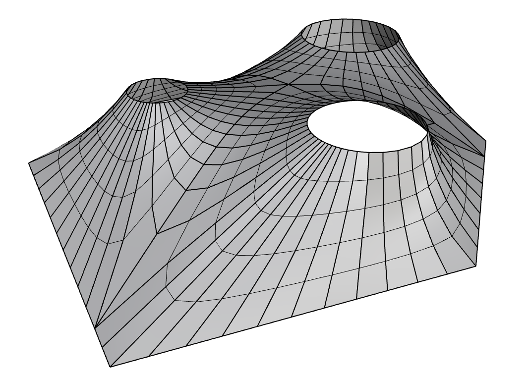
They wanted a pipeline that can automate most of the design, simulation and production drawing workflows. The overall diagram of the algorithm that I developed is shown below. It was highly inspired by the previous work by Anders Holden Deleuran.

The process went through many stages of trial and error. The developed methodology reflects the client’s needs and their work logic.
Here are some of the challenges that came around during the work.
Division Method
Once the overall mesh was created there are several methods that can be used in order to divide the mesh into individual stripes that can be later flattened out. Here many questions need to be addressed in order to find the best workflow.
Method 1: Equal division count
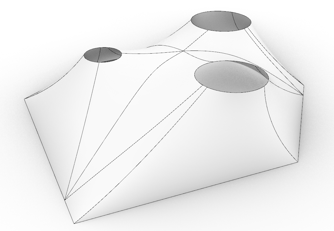
The first very basic method to try would be to take the boundary and peak curves. Divide them with equal amounts and connect corresponding points. While for some cases this may work. In others, this method would be problematic. Based on the peak alignment and boundary shape, you may get some stripes that reaching far points whether you would prefer them to find a connection point much nearer.
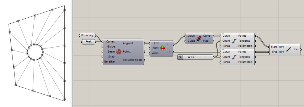
Method 2: Nearest point on peak
The next method to try would be to at first divide the boundary, then find the nearest point on the peak for each point on the boundary and then connect them. This resolves the problem from the previous case with skewed stripes however in this case we can see that the widths on the peak rim may vary a lot. In some cases, this method may result in coinciding nearest points on the peak which will lead to triangular stripes.
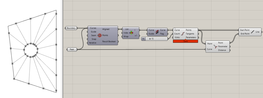
Method 3: Combining Mesh Strips
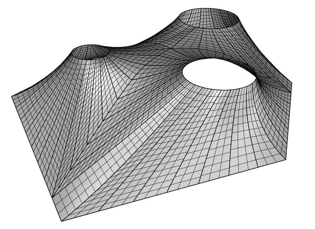
So the next method would be to do the following. Since we already have the initial mesh that was form-found. It already has its internal mesh stripes. So why don’t we just group them together in some quantities (2,3,4 etc.) and take the overall boundary of the resulting mesh as one stripe. This method has some advantages and drawbacks. The advantages are that it doesn’t have the problems of the earlier two methods. The disadvantage is that in some cases since we are taking the shapes from the Kangaroo simulated mesh, especially around the island seams, we may get curves that are unnaturally tilted to one side. This is a result of the K2 simulation forces.

Method 4: Geodesics
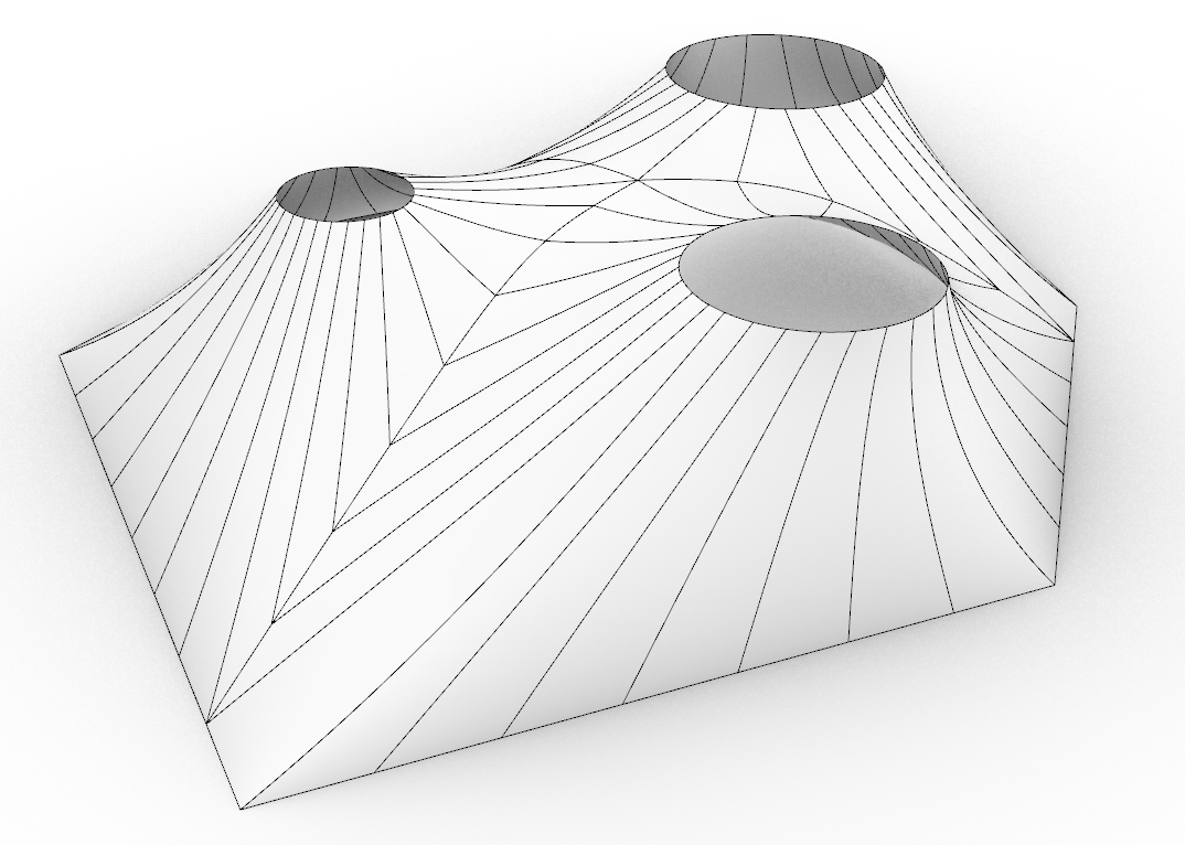
So the final method that proved to be the best was a combination of the above methods together with the introduction of geodesic curves. So here, what we initially do is using the initial form-found mesh we reconstruct a collection of surfaces. Note that here we are supplying the information about the island corners all the way to this stage. Then since we now have surfaces instead of meshes, we can construct geodesic curves on them that connect to points on the boundary to the points on the peaks. In this case, the corners may have two separate geodesic curves per surface so we can just take their tween and use instead for both. Then the geodesics are used, coupled with the fragments on the boundary and peaks to construct new untrimmed surfaces representing each strip. These stripes are then remeshed for flattening. Note that in this case the remeshing density can for each one can be independent.
Stripe Shapes
Matching seams
First, we need to understand whether the cut seams from various islands need to coincide or not. This is a matter of production preference and technology. In our case, it was best to keep them aligned and not like in the image.

Corners
The next question is about the corners. Do we want the seams to run over the corners (2) or do we want the boundary corners also to act as cut seams (1)? Here again, the production technology played a role so we decided to divide by the corners as well.

Unrolling meshes with double curvature
Normally you may want to have stripes of meshes with quad/triangle faces. In this case, you can use basic unroller components (like the one below that comes from Kangaroo) that will straighten out the mesh ribbon for you.


However, in case, you have meshes that are not just plain stripes (like in the example below, when we change the U division to be greater than 1), the unroller can no longer work. Even in this case where we know that the mesh doesn’t have a double curvature so theoretically, it should be able to do this. Alas, this component doesn’t make a curvature check and looks only at the mesh structure.
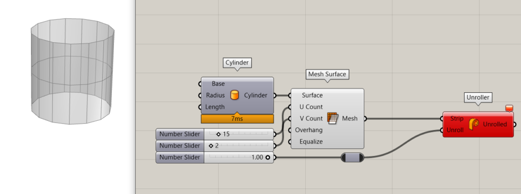
Now in our case, we had mesh stripes that not only had many V divisions but also had a double curvature.
Another method that could be tried is the unrolling of a polysurface. RhinoCommon library has a built-in unroller class that allows polysurfaces to be unrolled. Several plugins have components that contain this functionality (Pufferfish, Lunchbox etc). I gave it a try. Converted meshes to breps and unrolled with such a component, but here the integrity mesh is broken. So whenever unrolling becomes impossible it makes a cut like in the image below.
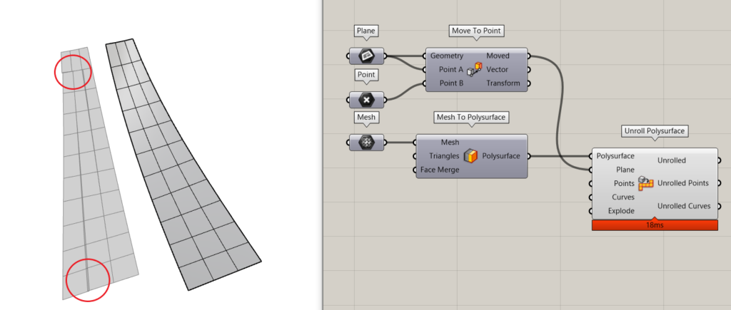
In this case, I needed to create a workaround that would function in a totally different way. Now note that double curvature surfaces cannot be flattened out without losing something (like distances between points, areas, angles). So a flattened here would have much more parameters than just an unroll number 0-1. We must be able to tell which aspects of the mesh are more important. Like the mesh-edges should be preserved but the angles can be violated or vice-versa or some compromised in between.
For this, I used a K2 Zombie simulation that had three main goals.
- Preserve the Lengths of edges
- Preserve the internal angles between the edges
- Planarize the overall mesh

This workaround made worked and the final results were acceptable.
